
About halfway through the summer Andrew Jones handed me a helmet sized acrylic dome with the simple request to build a database of fully relightable skin samples. Andrew Jones is yet another of ICT’s fantastic research team, and a specialist in 3D autostereoscopic displays. He had previously used the entire ICT Light Stage X, and a specialized macroscopic camera rig to produce skin microgeometry maps. Use of the full light stage severely limited potential subjects to those who could be brought to ICT and remain still for over thirty seconds.


The challenge for this project would be to reproduce the basic functionality of ICT’s Light Stage X as closely as possible in a portable package the size of a salad bowl. The Light Stage has over a thousand lights with known positions, each independently controlled. The miniature dome would not need nearly this many but the principle function had to stay the same. Each light source must be controllable individually or in groups, and have a known location relative to the center of the dome. Other aspects such as polarization and specularity of the light would also be important.
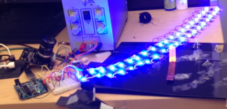
A common problem in LED lighting for photography and high speed video is the synchronizing of rolling shutter with the PWM signal used to dim the LEDs. When too slow an LED driver is used with a fast rolling shutter the result is a striated image wherein the lighting for each row of pixels cannot be predicted except in that it will be absolutely wrong. This was a problem I solved several different ways over my time at ICT. In this instance I had originally intended to make use of the PDM design from earlier in the summer but quickly found that the amount of wiring needed to control each LED from a Spartan 6 FPGA would be far too great to be done in one summer. The only reasonable course was to use a manufactured 3 color individually addressable LED strip. To avoid the rolling shutter problem I opted for an older and rather more expensive model from adafruite which could achieve a PWM base frequency of 1.2MHz. https://www.adafruit.com/products/306
Based on the LPD8806 LED driver this strip proved excellent for the purpose though I was disappointed that it boasted only a 7bit signal as opposed to the 8 or 10 bit grey-scale I was seeking. I was most impressed by this strips low power requirements requiring only a few watts to activate 172 LEDs and associated drivers.
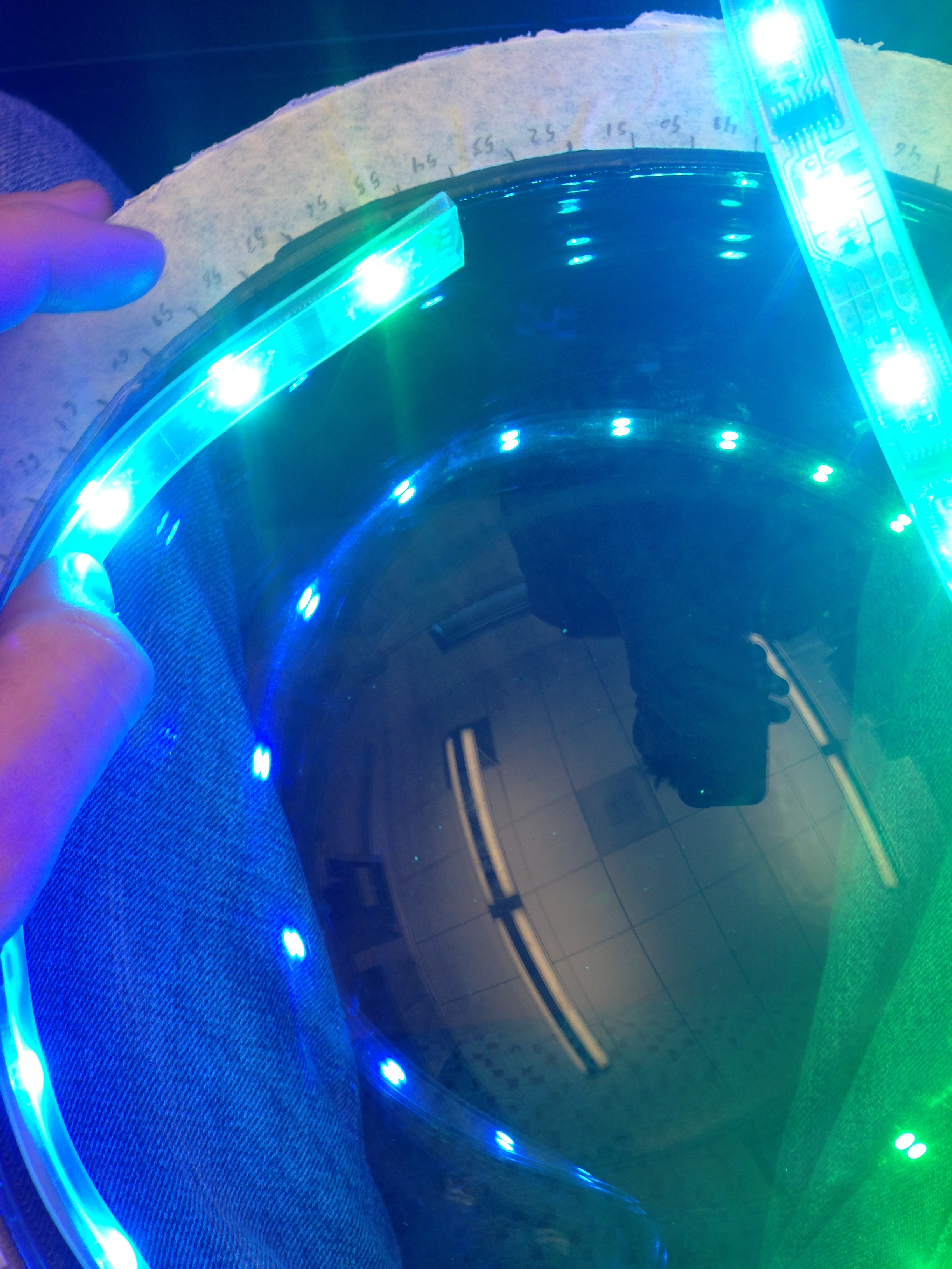
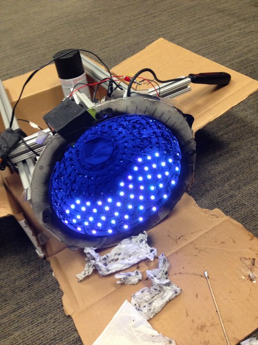
After disassembling the strips I spent a few hours finding the best arrangement within the dome. Achieving the maximum density of sources was the main goal but a regular and intuitive pattern was also important. The last consideration was ease of wiring.


The pattern chosen, using vertical strips required rewiring every four LEDs to connect to the next strip segment. While still less soldering than other designs this pattern required several hours of soldering inside the dome. Each strip segment required four connections to the next segment. A further problem, the uneven distribution of LED’s was precisely the opposite of what we needed. Since the purpose of the dome was to produce shadows of 3D geometry, we needed a higher density of LEDs close to the bottom where the induced shadows would be most pronounced. To solve this a second I added a second set of smaller, two LED segments which fit perfectly between the larger strips at the bottom. Learning from my prior experience soldering inside the dome I manufactured this strip before gluing it in place.
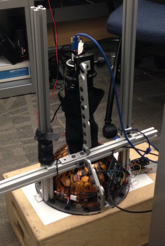
The next Stage was the mechanical mounting. This went surprisingly quickly thanks to ICT’s massive supply closet of prototyping hardware. The hardest part turned out to be cutting a circle from the top of the dome. A hot knife worked exceptionally well on the hard acrylic.
The frame was a bit bulky but cutting down the 8020 wasn’t a high priority until the end. The most important thing at this stage was demonstrating camera synchronization with the lights. Without synchronization the whole project would be a bust. Fortunately the Point Grey machine vision camera has a simple external trigger which only needed voltage step up to interface with the Arduino controller. With synchronization handled I still needed to control ambient lighting. From long years of experience as a theater tech I knew there is only one way to handle ambient lighting. Paint it Black. (Theater experience not necessary, though the Rolling Stones certainly are)

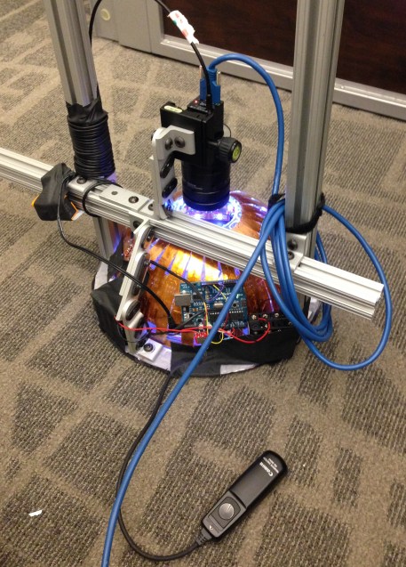
That was it the dome was functionally complete, still needed cleanup but it was time to run some stress tests. Tests ranged from running all LEDs for minutes at a time to test the power supply. To speed tests to see how fast we could get a full set of images.
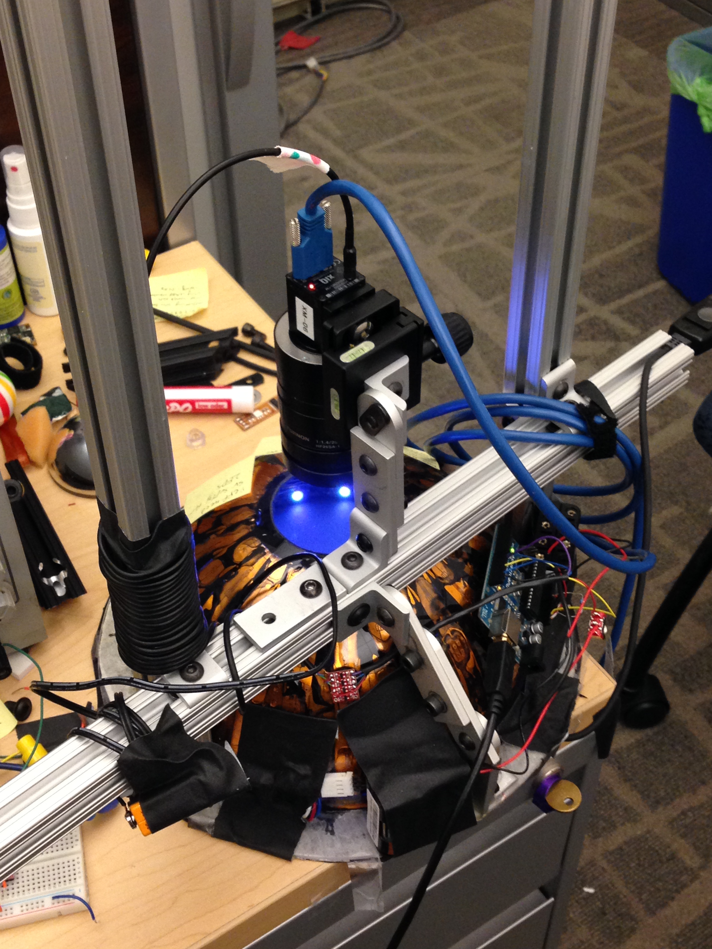
The last addition was a hood to keep ambient light from slipping in around the camera. Somehow I never thought to take pictures after the dome was cleaned up but here is the completed dome being calibrated for relative lighting intensity and position.

